TOSHIBA ASD-TB1-ACI PLC Processors Instruction Manual
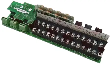
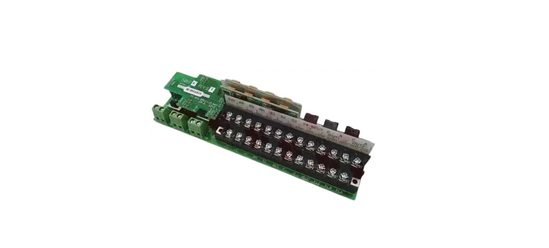
ASD-TB1-SIM9 Installation Procedure
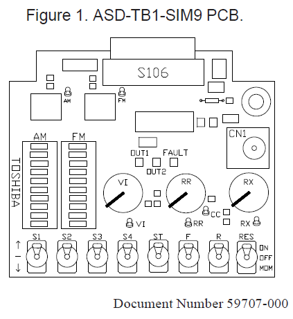
- The ASD-TB1-SIM9 is used to demonstrate the many powerful features of the 9-Series ASDs and may be
used with any of the 9-Series ASDs. - The ASD-TB1-SIM9 was developed to emulate the input/output control signals of the 9-Series ASDs.
- The simulated input signals of the ASD-TB1-SIM9 are provided via switches and pots.
- The switches simulate discrete input signals, such as relays and contactors — the pots simulate analog
inputs, which may be voltage or current. The ASD-TB1-SIM9 uses LEDs to provide the status of the AM,
FM, OUT1, OUT2, and Fault signals. - The ASD-TB1-SIM9 connects to the Control Board and is installed using same slide-in method as the
Terminal Board that is normally used with the 9-Series ASD.
WARNING
This procedure is to be performed by Qualified Personnel ONLY. See the Installation and Operation Manual of the ASD being used for the complete description of the discrete and analog operational applicable, and ASD safety precautions and requirements.
Ensure that the 3-phase input power to the ASD is off and that the circuit is properly locked out and tagged out as per your local, regional, and/or state regulatory agency.
Failure to do so may result in equipment damage, injury, or death.
To prevent electrical shock, ensure that the front cover of the 9-Series ASD has been secured before applying power to the unit.
Installation Procedure
- Open the front door of the 9-Series ASD and remove the lower front cover.
- Loosen the Torx® screw at the upper-right side of the Terminal Board.
- Remove the factory-installed Terminal Board from the 9-Series ASD.
- Insert the ASD-TB1-SIM9 into the 9-Series ASD. Ensure that the male S106 connector of the ASDTB1-
SIM9 seats securely into the female connector of the 9-Series ASD Control Board. - Secure the ASD-TB1-SIM9 using the Torx® screw in the upper-right side of the ASD-TB1-SIM9.
- The Torx® screw in the upper-right side of the ASDTB1- SIM9 does not require much torque to secure
the ASD-TB1-SIM9 into the 9-Series ASD. Once the Torx® screw begins to resist turning, less than ½
of a turn is required to tighten securely. - Replace the lower front cover and close the door of the 9-Series ASD.
Terminals and Features
- AM Terminal — Produces an output current that is proportional to the magnitude of the function assigned to this terminal (see the Installation and Operation Manual of the ASD being used for more information on the AM terminal settings).
- AM LED Indicator — A 1-to-10 LED module that produces a real-time visual indication of the magnitude of the function assigned to this terminal.
- FM Terminal — Produces an output current that is proportional to the magnitude of the function assigned to this terminal (see the Installation and Operation Manual of the ASD being used for more
information on the FM terminal settings). - Parameter F681 must be set to 0–10V to use the FM terminal with the ASD-TB1-SIM9.
- FM LED Indicator — A 1-to-10 LED module that produces a real-time visual indication of the
magnitude of the function assigned to this terminal. - S1 – RES Switches — Multifunctional programmable switch-activated discrete inputs (qty. 8).
- VI Potentiometer — Simulates the VI and the II analog input signals that are used to control the speed
or torque of the motor. - VI Terminal — Test equipment monitor for the simulated VI input signal.
- RR Potentiometer — Simulates the RR analog input signal that is used to control the speed or torque of
the motor. - RR Terminal — Test equipment monitor for the simulated RR input signal.
- RX Potentiometer — Simulates the RX analog input signal that is used to control the speed, torque,
and/or the direction of the motor. - RX Terminal — Test equipment monitor for the simulated RX input signal.
- CN1 — Backup Control voltage input connector.
- OUT1 Terminal — A discrete output terminal that may be programmed to provide an indication (open or
closed) that any 1 of the available functions of the ASD has taken place (see the Installation and Operation Manual of the ASD being used for more information on OUT1 terminal settings). - OUT2 Terminal — A discrete output terminal that may be programmed to provide an indication (open or
closed) that any 1 of the available functions of the ASD has taken place (see the Installation and Operation Manual of the ASD being used for more information on OUT2 terminal settings).