JVC HA-W600RF FM Cordless Headphones User Manual

SPECIFICATION
| General Specifications | |
| System | Radio Frequency (UHF stereo) |
| Modulation | Frequency modulation |
| Carrier frequency | 912.0 / 912.5 / 913.0 MHz (J/C Model), 863.5 / 864.0 / 864.5MHz (G/B Model) |
| Usable area (distance to reach) | Approx. 50 m /164 ft (J/C Model), 100 m /328 ft (G/B Model): using JVC measurement systems |
| Frequency response | 25 – 13,000 Hz |
| Distortion | Less than 3% (at 1 kHz) |
| Transmitter (J22320-001 : J/C Model, J22321-001 : G/B Model) | |
| Power requirements | DC12V(with the exclusive AC adaptor J34675-001(J/C Model)/J34676-001(G Model)/J34677-001(B Model)) |
| Audio input terminal | 3.5 mm dia. stereo mini jack |
| Input impedance | 36kW |
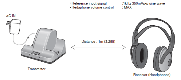
| Reference input level | 350 mV |
| Dimensions | 159 (W) ´ 114 (D) ´ 123 (H) mm (6.26″ ´ 4.49″ ´ 4.84″) |
| Mass | 280 g (9.9 oz) (without connection cord and AC adaptor) |
| Headphones (HA-W600RF) | |
| Power requirements | Rechargeable Ni-MH battery (1.2V) ´ 2 |
| Battery running time | 10 hours (when charged for 30 hours) |
| Mass | 250 g (8.8 oz) (with installed rechargeable battery) |
| Provided Accessories | |
| Instructions ´ 1, AC adaptor ´ 1, Connection cord ´ 1 (3.5 mm dia. stereo mini plug – 3.5 mm dia. stereo mini plug :
2.2 m (7.22 ft)), Conversion cord ´ 1(3.5 mm dia. stereo mini jack – RCA pin plug ´ 2 : 0.1 m (0.33 ft)),Rechargeable Ni-MH battery ´ 2,Plug adaptor ´ 1 (converts 3.5 mm dia. stereo mini plug to a 6.3 mm dia. standard stereo phone plug) |
|
Design and specifications subject to change without notice.
Safety Precautions
- This design of this product contains special hardware and many circuits and components specially for safety purposes. For continued protection, no changes should be made to the original design unless authorized in writing by the manufacturer. Replacement parts must be identical to those used in the original circuits. Services should be per- formed by qualified personnel only.
- Alterations of the design or circuitry of the product should not be made. Any design alterations of the product should not be made. Any design alterations or additions will void the manufacturers warranty and will further relieve the manufacture of responsibility for personal injury or property damage resulting therefrom.
- Many electrical and mechanical parts in the products have special safety-related characteristics. These characteristics are often not evident from visual inspection nor can the protection afforded by them necessarily be obtained by using replacement components rated for higher voltage, wattage, etc. Replacement parts which have these special safety characteristics are identified in the Parts List of Service Manual. Electrical components having such features are identified by shading on the schematics and by ( ) on the Parts List in the Service Manual. The use of a substitute replacement which does not have the same safety characteristics as the recommended replacement parts shown in the Parts List of Service Manual may create shock, fire, or other hazards.
- The leads in the products are routed and dressed with ties, clamps, tubings, barriers and the like to be separated from live parts, high temperature parts, moving parts and/or sharp edges for the prevention of electric shock and fire hazard. When service is required, the original lead routing and dress should be observed, and it should be confirmed that they have been returned to normal, after reassembling.
Leakage shock hazard testing
After reassembling the product, always perform an isolation check on the exposed metal parts of the product (antenna terminals, knobs, metal cabinet, screw heads, headphone jack, control shafts, etc.) to be sure the product is safe to operate without danger of electrical shock. Do not use a line isolation transformer during this check.
- Plug the AC line cord directly into the AC outlet. Using a “Leakage Current Tester”, measure the leakage current from each exposed metal parts of the cabinet, particularly any exposed metal part having a return path to the chassis, to a known good earth ground. Any leakage current must not exceed 0.5mA AC (r.m.s.).
- Alternate check method
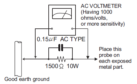
Plug the AC line cord directly into the AC outlet. Use an AC voltmeter having, 1,000Ω per volt or more sensitivity in the following manner. Connect a 1,500Ω 10W resistor paralleled by a 0.15μF AC-type capacitor between an exposed metal part and a known good earth ground. Measure the AC voltage across the resistor with the AC voltmeter. Move the resistor connection to each exposed metal part, particularly any exposed metal part having a return path to the chassis, and measure the AC voltage across the resistor. Now, reverse the plug in the AC outlet and repeat each measurement. Voltage measured any must not exceed 0.75 V AC (r.m.s.). This corresponds to 0.5 mA AC (r.m.s.).
Warning
- This equipment has been designed and manufactured to meet international safety standards.
- It is the legal responsibility of the repairer to ensure that these safety standards are maintained.
- Repairs must be made in accordance with the relevant safety standards.
- It is essential that safety critical components are replaced by approved parts.
- If mains voltage selector is provided, check setting for local voltage.
Caution
Burrs formed during molding may be left over on some parts of the chassis.
Therefore, pay attention to such burrs in the case of preforming repair of this system.
Critical parts for safety
In regard with component parts appearing on the silk-screen printed side (parts side) of the PWB diagrams, the parts that are printed over with black such as the resistor ( ), diode ( ) and ICP ( ) or identified by the ” ” mark nearby are critical for safety. When replacing them, be sure to use the parts of the same type and rating as specified by the manufacturer.
(This regulation dose not Except the J and C version)
DISASSEMBLY
Transmitter
In case of some problems arise in this transmitter unit, have to change the transmitter unit itself, due to avoid the law of radio regulation.
Receiver (Headphones)
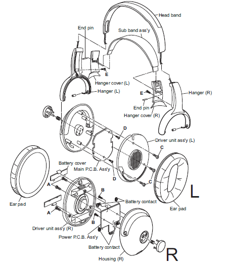
Remove the driver unit ass’y (R) and power P.C.B. ass’y
- Ear pad and battery cover are removed.
- Remove the three screws A attaching the driver unit ass’y (R).
- Remove the two screws B attaching the power P.C.B. ass’y.
- The solder of each wire connected with driver unit ass’y (R) and power P.C.B. ass’y is removed.
Please confirm that it is in the ditch where battery contact (four places) on the power P.C.B ass’y exists in housing (R) when you install the power P.C.B. ass’y in housing (R).
Remove the driver unit ass’y (L) and main P.C.B. ass’y
- Ear pad is removed.
- Remove the three screws C attaching the driver unit ass’y (L).
- Remove the two screws D attaching the main P.C.B. ass’y.
- The solder of each wire connected with driver unit ass’y (L) and main P.C.B. ass’y is removed.
Remove the sub band ass’y
- Remove the two screws E attaching the hanger cover (L) and (R)
- Right and left end pin is removed.
Remove the head band ass’y
Prior to performing the following procedure, remove the driver unit ass’y (L/R), power P.C.B. assay, main P.C.B. ass’y, sub band ass’y.
Head band ass’y is removed while drawing out the wire from ditches that exist in hanger (L/R) and head band ass’y.
TROUBLESHOOTING