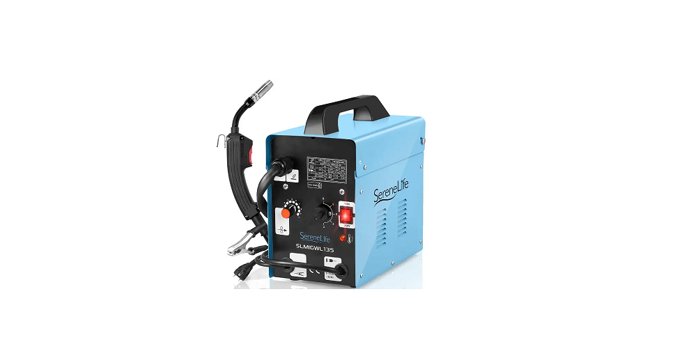
Serenelife SLMIGWL135 Welding Machine User Manual
WARNING!
Read and understand all safety warnings and instructions carefully before using this machine. Failure to follow the warnings and instructions may result in electric shock, fire, and/or serious injury. Save this manual for future reference.
WELDING PREPARATION:
An important factor in making a satisfactory weld is preparation. This includes studying the process and equipment and practicing welding before attempting to weld the finished product. An organized, safe, ergonomic, comfortable, and welllit work area should be prepared for the operator. The work area should specifically be free of all flammables with both a fire extinguisher and a bucket of sand available.
To properly prepare for welding with your new welder, it is necessary to:
- Read the safety precautions at the front of this manual.
- Prepare an organized, well-lit work area.
- Provide protection for the eyes and skin of the operator and bystanders.
- Attach the ground clamp to the bare metal to be welded, making sure of good contact.
- Make sure that the wire-roller groove in the roller corresponds to the diameter and type of wire being used.
- Plug the machine into a suitable outlet.
FIRE PRECAUTIONS
- All flammable materials MUST be removed from the welding area.
- DO NOT strike an Arc on or near the gas cylinder.
- DO NOT attempt to weld fuel or gas containers unless adequate procedures have been taken to ensure that no vapor remains. Fuel tanks should be thoroughly steam cleaned before welding.
WELDING FUMES
Toxic gases are given off during the MIG welding process. Always use in a well-ventilated area.
HEAT
Wear welding gloves at all times whilst welding. They will protect the hands from ultraviolet radiation and direct heat of the arc. It is also recommended that overalls are worn.
IMPORTANT:
- These units should never be exposed to rain or snow.
- Do not use it in a wet or damp environment.
- Never use to thaw or heat up frozen pipes.
- this unit should be connected to the main supply through a circuit breaker.
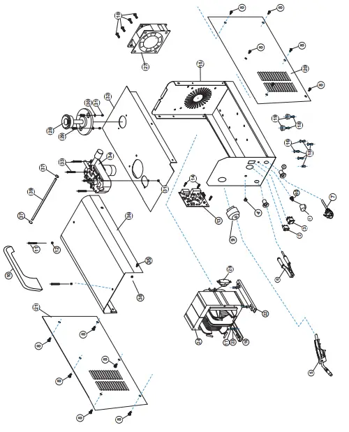
PARTS DESCRIPTION
| 40 | 2.2k potentiometer | 1 |
| 39 | Ø4 rebar | 1 |
| 38 | M4 self-locking nut; stop nut | 2 |
| 37 | Ø4 Riveting fastening | 4 |
| 36 | The case cover plate | 1 |
| 35 | M4*12 bolt | 2 |
| 34 | Board potentiometer in chassis | 1 |
| 33 | M4*50 Cross screw with half round head | 4 |
| 32 | Chassis plate | 1 |
| 31 | M4 nut | 6 |
| 30 | M4 flat gasket | 2 |
| 29 | M4*12 Cross screw with half round head | 2 |
| 28 | Wire holding plate | 1 |
| 27 | Fan | 1 |
| 26 | adapting piece | 1 |
| 25 | thermal protector | 1 |
| 24 | transformer | 1 |
| 23 | M5 spring washer | 4 |
| 22 | Transformer backing plate | 1 |
| 21 | left side plate | 1 |
| 20 | right side plate | 1 |
| 19 | The bottom of the rubber bead | 4 |
| 18 | M5*12 Cross screw with half round head | 14 |
| 17 | M5 nut | 8 |
| 16 | M5 flat gasket | 12 |
| 15 | Chassis backplane | 1 |
| 14 | M3*25 Cross screw with half round head | 4 |
| 13 | Feed control circuit board | 1 |
| 12 | M5 nut | 1 |
| 11 | M5*35 Philip’s head screw | 2 |
| 10 | hand shank | 1 |
| 9 | M 27*1.5 clip M27*1.5 | 1 |
| 8 | ST5*12 Cross screw with a half-round head | 12 |
| 7 | Plug | 1 |
| 6 | earth clamp | 1 |
| 5 | welding gun | 1 |
| 4 | indicator light | 1 |
| 3 | power switch | 1 |
| 2 | switch | 2 |
| 1 | Potentiometer knob | 1 |
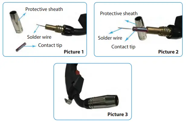
NOTICE:
While installing the new solder wire. Please take off the protective sheath and contact tip of the MIG torch (see picture 1). Then press the Mig torch switch to let the wire out till 3.5cm. At last, assemble the protective sheath and contact tip back (see pictures 2 and 3). To avoid the wire block the contact tip.
SETTING UP THE WELD:
- Make practice welds on pieces of scrap the same thickness as your intended workpiece to practice the technique before welding anything of value.
- Clean the weld surfaces thoroughly with a wire brush or angle grinder; there must be no rust, paint, oil, or other materials on the weld surfaces, only bare metal.
- Use clamps (not included) to hold the workpieces in position so that you can concentrate on proper welding techniques. The distance (if any) between the two workpieces must be controlled properly to allow the weld to hold both sides securely while allowing the weld to penetrate fully into the joint. The edges of thicker workpieces may need to be chamfered (or beveled) to allow proper weld penetration.
- Clamp Ground Cable to bare metal on the workpiece near the weld area, or to the metal workbench where the workpiece is clamped.
- Set the Wire Speed Dial and the Current Switch to the desired settings. Refer to the chart on the Welder or the chart on the facing page. WARNING: Do not switch the current while welding.
- Flip the Power Switch to the OFF position, then plug the Welder into a dedicated, 120 VAC, 20 A circuit with delayed action type circuit breaker or fuses.
- Hold the Gun, without touching the Trigger, with the wire and tip clearly away from any grounded objects. Then, turn the Power Switch to ON.
ASIC WELDING TECHNIQUE
- Press (and hold) the Trigger and contact area to be welded with electrode wire to ignite the arc.
- For a narrow weld, you can usually draw the wire in a steady straight line. This is called a stringer bead. For a wider weld, draw the wire back and forth across the joint. This is called a weave bead.
- Hold the Gun in one hand and the face shield in the other. If a hands-free welding shield is used, then both hands can be used to control the Gun.
- Direct the welding wire straight into the joint. This gives an angle of 90° (straight up and down) for butt (end to end) welds and an angle of 45° for fillet (T-shaped) welds.
- The end of the Gun should be tilted so that the wire is angled anywhere in between straight on and 15° in the direction you are welding. The amount of tilt is called the drag angle.
- The welding wire should extend no more than 1/2″ past the tip. This distance is called stick out or CTWD.
- After welding the test weld on a piece of scrap for a few seconds, stop, and check your progress.
- When the weld is complete, lift the Gun and welding wire clearly away from any grounded object, and turn the Power Switch off.
- Set the Gun down on a heat-proof, electrically non-conductive surface. Unplug the Power Cord.
SELECTING THE WELDING WIRE
This welder uses only four or eight-inch spools of 0.030-inch (0.8mm) self-shielding flux-core wire. Steel from 24 gauge up to 1/4-inch thick can be welded with 0.030 -inch wire. Larger diameter wire will be less capable with thicker materials, will not increase your deposition rate, and may overdraw your AC power source.
NOTE:
- If a spool has developed heavy oxidation, the only solution to the problem is to discard the spool of wire.
- If you have an oxidized spool of wire, do not discard it until you have unspooled a few turns of wire to see if the wire farther down on the spool is in usable condition. If it is not, discard the spool.
TROUBLESHOOTING
| PROBLEM | POSSIBLE CAUSES |
| Weld deposit too thick | • Welding voltage too low.
• Torch moved over the work piece too slowly. |
| Weld deposit incomplete and stringy | • Torch moved over the work piece too quickly. Rust, paint or grease on the work piece. |
| Arc unstable, excessive spatter and weld porosity | • Torch held too far from the work piece.
• No gas – check bottle content, connections and regulator settings. • Incorrect gas for material. |
|
Wire repeatedly burns back |
• Torch held too close to the work piece.
• Break in the welding circuit Possible causes: • Incorrect size of contact tip for wire. • Contact. tip damaged – replace. • Contact tip loose – tighten. • Feed rollers worn – replace. • Welding wire corroded – replace. • Pressure roller adjustment incorrect – adjust. • Pressure roller sticking – lubricate or replace. • Wire tangled on reel |
|
Lack of weld penetration |
• Welding output too low.
• Wire feed speed too low. • Torch moved too fast. |
| Burning holes in work piece | • Welding out put too high.
• Torch moved erratically 0r too slowly. |
| No arc produced | • Earth lead or torch cable in open circuit.
• Poor earth clamp connection |
| Welder does not operate
(mains indicator not lit) |
• Check mains connection.
• Check supply fuse. |
| Welder does not operate with trigger pressed | • Check torch trigger and it’s connections.
• Thermal overload cut out – allow to cool. |
ROUTINE MAINTENANCE
Electrical repairs must only be carried out by a qualified or approved engineer.
Welding Cables:
Regularly inspect their connections. Torch: Regularly dean the contact tip and shroud to remove spatter that will eventually disturb the flow. Spraying the tip and shroud with anti-spatter spray can reduce the build-up of the spatter. Replace the tip periodically to maintain good electrical contact between the tip and the wire. Blow clean dry air through the torch liner from time to time to ensure the wire passes freely through it If this has no effect the liner should be replaced.
WIRING DIAGRAMS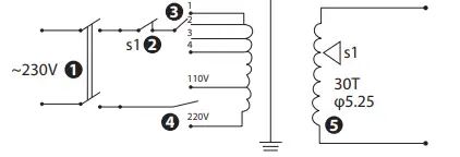
- Switch
- Thermal Protection
- Settings
- Settings
- Primary Winding
- Secondary Winding
- Rectifier
4 POWER SETTINGS CONNECTION:
- 1. 230V a.d. 35A
- 2. 230V b.d. 50A
- 3. 230V a.c. 75A
- 4. 230V b.c. P0A
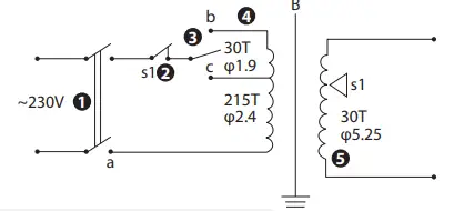
- Switch
- Thermal Protection
- Settings
- Settings
- Primary Winding
- Secondary Winding
- Rectifier
2 CURRENT SETTINGS CONNECTION:
- 1. a.c. PoAmp
- 2. a.b. bomb
FEATURES
- Easy to Use and Convenient to Carry
- Powerful and Rugged MIG Welding Machine up to 120 Amp Output
- Nice Machine Appearance and Screen Printing
- Anti-corrosion & Water Resistant Metal Machine Case
- Easy to Read the Numbers of Scale
- Test Data Supports Stable Performance and Output Voltage
- Protects Components and Transformer from Corrosion and Damage
- 10% Rated Duty Cycle, Weld for One Minute, Rest for Nine Minutes
- Adjustable Welding Speed up to 6.7m per Minute
- Supports Dual Voltage 110V/220V, Wire Feeder 1-12V
- Accepts 0.8-1.0mm Flux-Cored Wire
- 1.35KVA/4.2KVA Maximum and Minimum Power
- 6.8mm of Maximum Thickness of Metal
- Allows to Weld Steel up to 0.24-0.3 inches Plate Steel
- Automatically Adjust the Inverter Pulse Width through Closed-Loop Control to Ensure the Output Stability.
WHAT’S IN THE BOX
- Welding Machine
- Welding Gun
- Ground Wire Clip (1.6 meters)
- Brush
- Protective Mask
- 2.5m²1.8m Big USA Plug
TECHNICAL SPECS
- Construction Material: Low Carbon Steel, Low Alloy Steel, and Stainless Steel
- Power Supply: 110V/220V
- Maximum Input Current: 110V/8A, 220V/19A
- Frequency Response: 50/60Hz
- Rated Input Power: 4.2KVA
- Current & Voltage Adjustment Range (MIG) : 60A/17V-130A/20.5V
- 40°C 60% Utilization Factor Output (MIG, A/V): (56A/16.8V)
- 40°C 100% Utilization Factor Output (MIG, A/V) :(43A/16.2V)
- No-load Voltage: 31V
- Usable Wire: 0.02”-0.04” -inch
- Wire Feed Rate: 13m/min
- Power Factor: 0.93
- Efficiency: 93%
- Shell Protective Grade: IP21S
- Insulation Grade: H
- Welding Output: 60-130A, AC
- Capacity: 18 gauge (0.039″) to 3/16″ (0.24″) mild steel only
- * Not for welding aluminum
- Duty Cycle: 10% @130A
- Open Circuit Voltage: 20.5V
- Welder Tips / Wire Size Installed tip will accept 0.031″ Flux-Core wire
- Wire Spool Capacity: 2.2 lbs. Spool
- Recommended Circuit Breaker: 30A time-delay (slow-blow) breaker (30A for maximum performance)
- Extension Cord Recommendations: 3 conductor #12A or larger up to 4.9 ft.
- Generator Requirements: Minimum 4,000W continuous output with no low-idle function (or low-idle off)
- Product Dimension (L x W x H): 16.5” x 10” x 15” -inches